
Why Is Grounding Wire Important for Electrical Safety?
A Grounding Wire is a quiet but critical part of a safe electrical system. It provides a low-resistance path for unwanted current when insulation fails or a metal case becomes energized. Instead of passing through a person, fault current can travel through the grounding path and help trip a circuit breaker. The result may be a brief spark, a sudden click, and a safer outcome.
Electricians regularly inspect grounding connections in outlets, panels, appliances, and junction boxes. A loose green or bare copper wire can remain unnoticed for years. Then one damaged cord changes everything. Grounding does not prevent every electrical accident, and it cannot replace correct wiring, protective devices, or careful maintenance. That limitation matters.
Professional installers follow applicable electrical codes and verify continuity with suitable testing equipment. They also examine bonding, grounding electrodes, breaker ratings, and connections inside the service panel. Homeowners may notice a missing ground pin or a warm outlet, but these signs require qualified attention. Guessing can be dangerous. I have seen how a small connection receives little attention until a fault exposes the weakness. That is the part worth questioning: does an apparently working circuit truly provide a safe path during failure? Reliable electrical safety depends on tested details, documented installation, and timely repairs. A Grounding Wire may seem ordinary, yet its value becomes clearest when something goes wrong. Safety is often quiet. That is why it deserves respect.
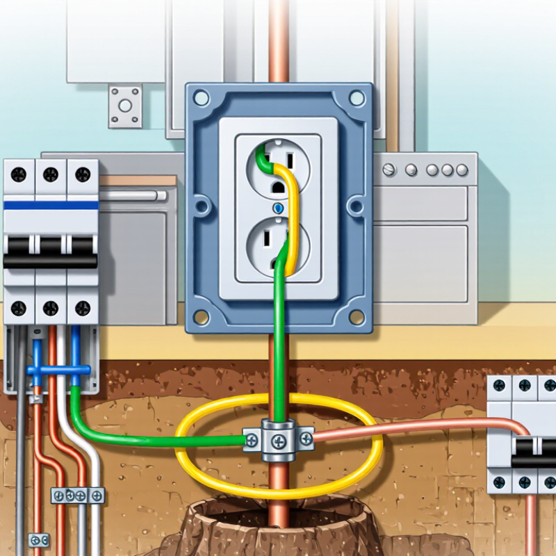
What Is Grounding? NEC 250.4’s Effective Fault-Current Path
Grounding is not merely a wire driven into soil. Under NEC 250.4, the installation must provide an effective fault-current path. That path must be permanent, continuous, and low impedance. It must safely carry fault current back to the source. Then, the overcurrent device can open quickly. That is the point.
A green wire can look reassuring. It proves little. During an inspection, check bonding jumpers, metal raceways, equipment grounding conductors, and panel terminations. A loose connection may leave a metal enclosure energized while the breaker remains closed. The grounding electrode helps stabilize system voltage, but it usually cannot carry enough fault current to trip a breaker. The return path matters more during a fault.
NFPA analysis of 2012–2016 data estimated an annual average of 35,150 U.S. home fires involving electrical distribution and lighting equipment. These fires caused about 470 civilian deaths, 1,100 injuries, and 1.3 billion dollars in direct property damage. The figures do not prove that grounding prevents every fire. They do show why fault-current design deserves attention. In practice, damaged conductors, improper terminations, and missing bonding connections create difficult surprises. I have to admit, visual inspection alone is imperfect. Continuity and impedance testing can reveal problems hidden behind clean covers. A complete path is more important than a convincing appearance.
Why Is Grounding Wire Important for Electrical Safety?
What Is Grounding? NEC 250.4’s Effective Fault-Current Path
| Safety Dimension | Verified Electrical Principle | How It Protects People and Equipment | Key Inspection Indicators | Primary NEC Reference |
|---|---|---|---|---|
| Grounding | Grounding connects electrical systems or equipment to earth through a grounding electrode system. | It helps stabilize the electrical system voltage to earth and provides a reference for the system. | Grounding electrode conductors are properly connected, protected from physical damage, and terminated at approved grounding electrodes. | NEC 250.4(A); NEC 250.50 |
| Bonding | Bonding electrically connects normally non-current-carrying metal parts, raceways, enclosures, and equipment grounding conductors. | Bonding places exposed conductive parts at substantially the same potential and supports a reliable fault-current path. | Metal enclosures, raceways, cable armor, and equipment grounding conductors are electrically continuous and securely connected. | NEC 250.4(A)(3); NEC 250.96 |
| Effective Fault-Current Path | The fault-current path must be permanent, continuous, and capable of safely carrying the electrical current likely to be imposed by a ground fault. | A low-impedance path allows fault current to return to the source rather than remaining on exposed metal surfaces. | Check for loose terminations, missing bonding jumpers, damaged conductors, improper modifications, or paths that depend on earth alone. | NEC 250.4(A)(5) |
| Overcurrent Protection | Ground-fault current should be sufficient to operate the circuit’s overcurrent protective device within the required conditions. | Opening the breaker or fuse removes power from the faulted circuit and limits shock, fire, and equipment hazards. | Verify conductor sizing, overcurrent-device rating, termination integrity, and continuity of the equipment grounding path. | NEC 250.4(A)(5); NEC 110.10 |
| Equipment Grounding Conductor | An equipment grounding conductor provides a designated conductive path for fault current from equipment back to the source. | It helps ensure that a fault on a metal enclosure produces protective-device operation instead of leaving the enclosure energized. | Confirm that the conductor is present, correctly sized, properly terminated, and connected at both the equipment and supply ends. | NEC 250.118; NEC 250.122 |
| System Bonding Point | For grounded systems, the grounded conductor is bonded to the grounding electrode system at the service or other permitted system bonding point. | The bonding connection establishes the intended reference and provides a return path for certain fault conditions. | Downstream panels should not contain unintended neutral-to-ground connections where the installation requires separation. | NEC 250.24; NEC 250.30 |
| Grounding Electrode System | All grounding electrodes present at a building or structure are generally required to be bonded together to form a grounding electrode system. | Bonding available electrodes helps create a coordinated grounding system and reduces differences in potential between electrodes. | Inspect building steel, metal water pipe, concrete-encased electrodes, ground rings, and supplemental electrodes where applicable. | NEC 250.50; NEC 250.53 |
| Earth Is Not the Fault-Clearing Path | The earth has relatively high impedance compared with metallic conductors and is not normally an effective path for clearing line-to-ground faults. | A grounding electrode connection alone generally cannot carry enough fault current to reliably open a branch-circuit breaker. | Do not treat a ground rod or other electrode as a substitute for an equipment grounding conductor or bonding path. | NEC 250.4(A)(5); NEC 250.54 |
| Continuity and Mechanical Security | Grounding and bonding connections must remain electrically continuous and mechanically secure under normal operating conditions. | Loose, corroded, painted, or damaged connections can increase impedance and interrupt the intended fault-current path. | Examine terminal torque, corrosion, conductor damage, prohibited paint or coatings at bonding points, and physical protection. | NEC 110.14; NEC 250.96 |
| Shock Hazard Reduction | Grounding and bonding reduce the duration and likelihood of dangerous voltage on accessible conductive parts; they do not replace safe work practices. | Rapid fault clearing and proper bonding reduce the time a person could be exposed to hazardous touch voltage. | Use qualified personnel, de-energize where required, apply lockout/tagout procedures, and verify absence of voltage before work. | NEC 250.4; OSHA 29 CFR 1910.333 |
| Ground-Fault Circuit Interrupter | A GFCI monitors the balance of current in the circuit and interrupts power when the outgoing and returning currents differ by a hazardous amount. | It provides supplementary protection against electric shock, especially in locations where contact with grounded surfaces or water is possible. | Test using the device’s test function at the required intervals and confirm correct line/load wiring where applicable. | NEC 210.8; NEC 406.4(D) |
| Inspection Limitation | Visual inspection alone cannot prove that a fault-current path has sufficiently low impedance or that every connection is electrically continuous. | Electrical testing and verification can identify hidden defects that may not be visible during a routine inspection. | Use qualified testing methods appropriate to the installation, including continuity, polarity, bonding, and protective-device verification. | NEC 110.3(B); NEC 250.4 |
Reference note: NEC requirements can vary by edition, installation type, and local adoption. The locally adopted electrical code and the authority having jurisdiction govern the final installation requirements.
Related Posts
-
China Best Grounding Wire Manufacturers for Global Buyers
-
How to Choose the Right Grounding Wire for Your Project?
-

The Complete Guide to Choosing the Best Grounding Wire for Your Needs
-
7 Essential Benefits of the Best Grounding Cable for Global Buyers
-

Discover the Top Alternatives to Best Battery Cable Wire for Your Global Sourcing Needs
-

Discover the Advantages of Using Power Cord Extension for Your Electrical Needs