
How to Choose the Right Grounding Wire for Your Project?
Choosing the right Grounding Wire is not a minor detail. It is a core decision affecting safety, equipment performance, and inspection results. The correct choice depends on fault-current capacity, conductor material, installation method, environmental exposure, and local electrical requirements.
Mike Holt, a respected electrical educator, puts the principle plainly: “The grounding conductor provides a low-impedance path for fault current.” That path must remain dependable when insulation fails or metal enclosures become energized. A wire that looks adequate on a workbench may perform poorly in a damp trench, crowded conduit, or corrosive industrial space.
Start with the system’s voltage, available fault current, and overcurrent protection. Then verify the required size from the applicable electrical code. Copper offers excellent conductivity and flexibility. Aluminum can reduce cost and weight, but it needs careful termination and corrosion control. Bare, insulated, and covered conductors each suit different environments.
Check the details.
Field conditions matter.
A Grounding Wire installed outdoors may need stronger mechanical and moisture protection. In a panel, loose terminations can create heat, noise, or dangerous touch voltage. Experienced electricians inspect routing, bonding points, fasteners, and surface preparation instead of trusting labels alone.
Some project guides oversimplify conductor selection. That is a weakness worth acknowledging. Wire size is important, but it is not the entire grounding system. Soil conditions, electrode connections, bonding continuity, and workmanship also influence performance. A qualified electrician should confirm the final design before installation, especially where local rules or unusual equipment apply.
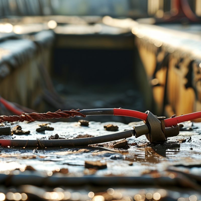
Define the Purpose and Safety Requirements of the Grounding Wire
A grounding wire gives fault current a low-resistance path back to the source. This path helps protective devices disconnect power quickly. Define its purpose before selecting its size or material. An equipment grounding conductor protects people from energized metal enclosures. A grounding electrode conductor connects the electrical system to grounding electrodes, such as rods or building steel. These functions are related, but they are not interchangeable.
Safety requirements depend on the circuit voltage, overcurrent protection, installation method, and local electrical code. Wire size must match the circuit’s protective device, not only the equipment’s visible size. Copper is common, while aluminum may require special terminations and careful preparation. Check insulation ratings, moisture exposure, temperature limits, and corrosion risks. Keep the route short, secure, and free from sharp bends. Never use a neutral conductor as a substitute for an equipment ground.
Small details matter.
At the panel, remove paint from bonding points when required, then tighten connections to the specified torque. Loose terminations can heat slowly and remain unnoticed. In damp areas, use approved corrosion-resistant fittings and protect exposed conductors from physical damage. A continuity test can reveal an open path, but it does not prove every connection is safe. De-energize the circuit before inspection, and have a qualified electrician verify the installation. I have seen otherwise neat wiring fail because one termination was never checked. That mistake is easy to repeat when schedules are tight. Review the complete circuit, not just the wire.
How to Choose the Right Grounding Wire for Your Project? - Define the Purpose and Safety Requirements of the Grounding Wire
| Grounding Function | Primary Purpose | Typical Applications | Suitable Conductor Options | Sizing Basis | Key Safety Requirements |
|---|---|---|---|---|---|
| Equipment Grounding Conductor (EGC) | Provides a low-impedance path for fault current so the protective device can disconnect the circuit quickly. | Branch circuits, feeders, motor circuits, appliances, metal enclosures, and exposed conductive parts. | Copper or aluminum conductors; bare, covered, or insulated conductors where permitted. | Usually selected according to the rating of the upstream overcurrent protective device and the applicable electrical code. | Connect all grounding terminals securely; do not use the neutral conductor as a substitute for the EGC unless a specific code exception applies. |
| Grounding Electrode Conductor (GEC) | Connects the electrical system or service to the earth through a grounding electrode system. | Ground rods, concrete-encased electrodes, ground rings, building steel, and metal water piping where recognized as electrodes. | Copper is commonly used; aluminum may be permitted in suitable locations when protected from corrosion and physical damage. | Based on the largest ungrounded service or feeder conductor and the type of grounding electrode, subject to local code rules. | Protect from physical damage and corrosion; use approved connectors and maintain a continuous, mechanically secure connection. |
| Main Bonding Jumper | Establishes the intentional connection between the grounded circuit conductor and the equipment grounding system at the designated bonding point. | Service disconnects, separately derived systems, transformer secondary disconnects, and main distribution equipment. | Copper or aluminum, selected for the system and installed in accordance with the applicable code. | Sized according to the service or separately derived system conductor and the applicable electrical standard. | The neutral-to-ground bond should be located only at the permitted bonding point; downstream panels normally keep neutral and grounding paths isolated. |
| System Bonding Jumper | Connects the grounded conductor of a separately derived system to the equipment grounding system to provide a fault-current return path. | Transformers, generators, inverter systems, and other separately derived power sources. | Copper or aluminum conductors with insulation and termination methods suitable for the installation. | Determined from the derived system conductor size and the available fault current, following the governing code. | Install at the correct point in the derived system and verify that all metallic paths are bonded without creating unintended parallel neutral paths. |
| Supplementary Bonding Conductor | Reduces potential voltage differences between simultaneously accessible metal parts. | Electrical rooms, industrial facilities, communication rooms, data centers, and areas containing extensive metal services. | Copper is widely used because of its conductivity, flexibility, and ease of termination. | Selected according to the equipment, fault-current level, installation method, and local requirements. | Bond metal raceways, enclosures, piping, structural steel, and other accessible conductive parts with approved fittings. |
| Protective Earth Conductor for Outdoor or Wet Locations | Maintains a reliable fault-current path where moisture, soil contact, chemicals, or ultraviolet exposure may affect the conductor. | Outdoor equipment, photovoltaic systems, pumps, marinas, agricultural facilities, and underground or partially buried installations. | Copper or suitably rated aluminum with insulation, jacket, conduit, or corrosion protection appropriate to the environment. | Based on fault protection, installation method, mechanical protection, temperature rating, and environmental conditions. | Use wet-location-rated insulation where required; seal entries, prevent dissimilar-metal corrosion, and protect against abrasion and impact. |
- Define whether the conductor is an equipment grounding conductor, grounding electrode conductor, bonding jumper, or another type of protective conductor.
- Determine the system voltage, available fault current, overcurrent protection rating, conductor material, installation method, and ambient conditions.
- Choose insulation and cable construction suitable for dry, wet, corrosive, hot, outdoor, underground, or hazardous locations.
- Use approved lugs, clamps, terminals, raceways, and bonding fittings that are compatible with the conductor material.
- Verify conductor sizing, routing, color identification, separation, and termination requirements against the electrical code governing the project.
- Have the final design and installation inspected or verified by a qualified electrical professional, especially for services, generators, photovoltaic systems, and industrial equipment.
Note: Grounding-wire requirements vary by jurisdiction, system configuration, installation method, and environmental conditions. The applicable local electrical code and project specifications take precedence over general guidance.
Related Posts
-
The Complete Guide to Choosing the Best Grounding Wire for Your Needs
-
Top 5 Examples of the Best Automotive Wire for High-Performance Applications
-
2026 Top Power Cord Extension Types You Need to Know?
-
2025 Top 5 Welding Cable Products: Elevate Your Welding Game with These Must-Haves
-

Global Reach of Chinese Technology through Best Power Extension Quality Solutions
-
Understanding the Challenges in Choosing the Right Battery Connectors